In this post, I will show and explain how to move from a one-site Active/Active T0 to a multi-site T0 in Active/Standby mode. In order to do it I will use the AS path prepend and Failover Domain.
The version of NSX-T I used was 3.1.3.5.
Official NSX-T Documentation related to this topic: https://docs.vmware.com/en/VMware-NSX-T-Data-Center/3.1/administration/GUID-5D7E3D43-6497-4273-99C1-77613C36AD75.html
Old Design – One AS to rule them all
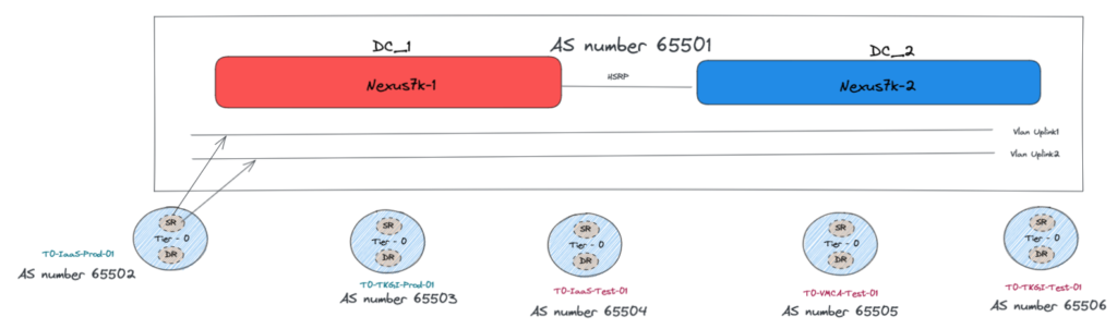
In this old design, we have a pair of Nexus 7k facing our T0s.
The two Nexus are using HSRP protocol and are seen as only one external router from a NSX-T T0 prospective with a unique BGP AS Number.
From the NSX-T configuration, it is impossible to have multiple AS number for a T0 so all of the T0 have their own AS number and they are all facing the External router with their own AS numbers.
We have two Uplink Vlans for Edges redundancy purpose.
New Design – Edge Bare metal servers
In our new design, the goal is to have a multi-site configuration.
We want to have separated external routers on each Datacenters in order to have “real” separated BGP routing entries into our Datacenters.
In this scenario, it is difficult to keep T0 in Active-Active mode as each NSX-T T0 have only one AS number.
We can take an example.
If we have the AS number “65555” for our T0 and it is hosted on 4 Edge VMs spread over the two Datacenters, the four are going to annouced “65555” as the local AS Number.
In this case, the TOR/Leaf switches are going to receive simultaneously the same AS number from different points in the Network.
This can create Asymmetric routing if a stateful traffic goes out through one route Edge_1->Leaf_1 and come back through another route Leaf_3->Edge_2.
One solution would be to have all the Edges on one site hosted in different servers connected to the same TOR Leafs. You will benefit of the Active/Active functionality however, you will have a lack of redundancy in case of the loss of the Datacenter.
The solution chosen here is to have T0 in Active/Standby mode across the two Datacenters.
We are going to increase the number of Edge Clusters and T0. Then we will attach our T1s among the different T0 created.
Some T0 are going to be Active on the first Datacenter DC_1 and Standby on the second DC_2.
Whereas some T0 are going to be Active on the second Datacenter DC_2 and Standby on the first DC_1.
This will allow us to use the Uplink bandwidth of both Datacenters.
In Active/Standby mode with Edge VMs, only one VM has the T0 Service Active.
This reduce drastically our Uplink bandwidth to two vNICs (VMXNET3).
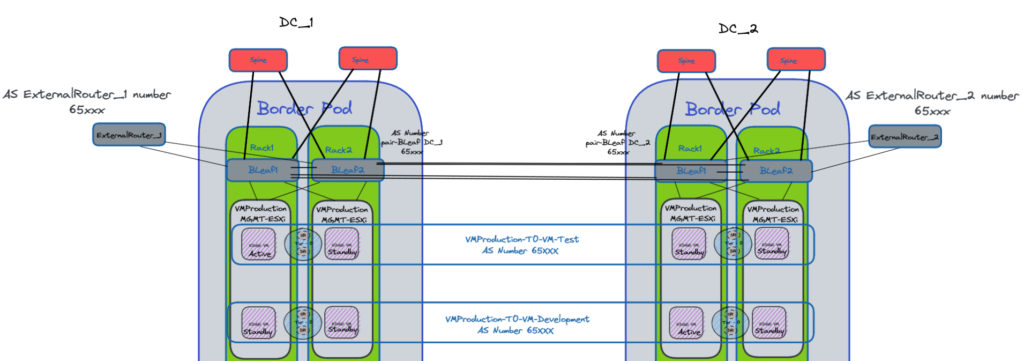
In our design, we will have two clusters including two bare metal servers for Production workloads and Edge VM clusters for Test and Development workloads.
The barre metal servers we use here have four interfaces 100 Gbps and two interfaces 25Gbps.
This allows us two have for one Active T0:
- 2x25Gbps for the Management.
- 2x100Gbps bandwidth for the Uplinks
- 2x100Gbps for NSX-T overlays with two TEPs.
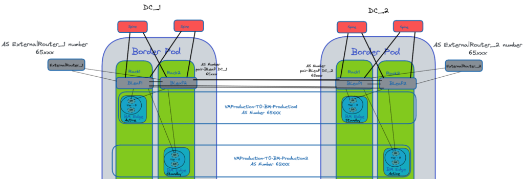
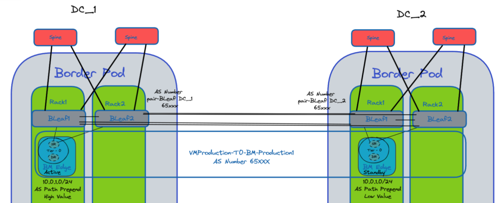
Below the new Design for the bare metal server clusters.
The two Border Leaf switches of each Datacenters have a peer link between them.
This best practise simplifies the design and troubleshooting as the two Leafs will have the same AS Number “AS Number pair-Bleaf DC_x”.
The Border Leaf switches are going to be the central point with all the BGP routing tables.
The will receive the routes from our NSX-T T0s, the Datacenters switches Fabric and the routes from outside our DC Fabric through the External Routers.
NOTE: In order to remove inter-DC excessive flows between T1 SR and T0 DR we removed the T1 SR.
As the only Service on T1 was SNAT (stateful) we moved this part to T0 SR are they are now working in Active/Standby mode.
New Design – Edge VM
Same approach here that we had with the Bare Metal servers.
The difference is that we do not have to take into consideration the cost of the Edges which was the case with the bare metal servers.
We can then have multiple Edge VMs in the same Edge VM cluster on each Datacenters.
Like this, we can use the Failover Domain feature of NSX-T in order to define a primary and secondary Datacenter.
If we lose the active Edge VM on DC_1 it will first use another Edge VM on the same DC_1.
If all the Edge VMs of the DC_1 are down then one of the Edge in DC_2 will have the Active T0 Service.
NSX-T Failover Domain
The configuration of the NSX-T Failover Domain as to be done through API calls only.
Configuration steps:
- Using the API, create failure domains for the two sites, for example, DC_1-Preferred_Site1 and DC_2-Preferred_Site1.
Set the parameter preferred_active_edge_services totruefor the primary site and set it tofalsefor the secondary site.
POST /api/v1/failure-domains {
"display_name": "DC_1-Preferred_Site1",
"preferred_active_edge_services": "true" }

POST /api/v1/failure-domains {
"display_name": "DC_2-Preferred_Site1",
"preferred_active_edge_services": "false" }- Using the API, configure an Edge cluster that is stretched across the two sites.
For example, the cluster has Edge nodes EdgeNode1A and EdgeNode1B in the primary site, and Edge nodes EdgeNode2A and EdgeNode2B in the secondary site.
The active tier-0 and tier-1 gateways will run on EdgeNode1A and EdgeNode1B.
The standby tier-0 and tier-1 gateways will run on EdgeNode2A and EdgeNode2B.
- Using the API, associate each Edge node with the failure domain for the site.
First call theGET /api/v1/transport-nodes/<transport-node-id>API to get the data about the Edge node.
Use the result of the GET API as the input for thePUT /api/v1/transport-nodes/<transport-node-id>API, with the additional property, failure_domain_id, set appropriately.
GET /api/v1/transport-nodes/<transport-node-id>
Response: {
"resource_type": "TransportNode",
"description": "Updated NSX configured Test Transport Node",
"id": "77816de2-39c3-436c-b891-54d31f580961" }

PUT /api/v1/transport-nodes/<transport-node-id> {
"resource_type": "TransportNode",
"description": "Updated NSX configured Test Transport Node",
"id": "77816de2-39c3-436c-b891-54d31f580961",
"failure_domain_id": "<UUID>" }- Using the API, configure the Edge cluster to allocate nodes based on failure domain.
First call theGET /api/v1/edge-clusters/<edge-cluster-id>API to get the data about the Edge cluster.
Use the result of the GET API as the input for thePUT /api/v1/edge-clusters/<edge-cluster-id>API, with the additional property, allocation_rules, set appropriately.
For example,
GET /api/v1/edge-clusters/<edge-cluster-id>
Response: {
"id": "bf8d4daf-93f6-4c23-af38-63f6d372e14e",
"resource_type": "EdgeCluster" }

PUT /api/v1/edge-clusters/<edge-cluster-id> {
"id": "bf8d4daf-93f6-4c23-af38-63f6d372e14e",
"resource_type": "EdgeCluster",
"allocation_rules": [     {
"action": {
"enabled": true,
"action_type": "AllocationBasedOnFailureDomain" }
} ], }
AS path prepend
We use the AS path prepend feature in order to prioritized a route rather than another.
In the example below the route 10.0.1.0/24 is annouced from both Datacenters to the Border Leaf switches of each DCs.
We apply a higher value to the primary preferred path.
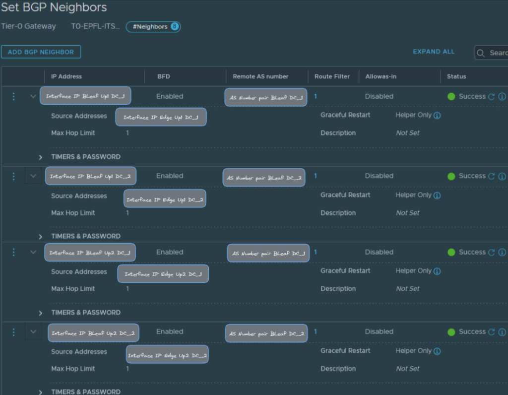
NSX-T Configuration steps
BGP Neighbors (Interfaces IPs & AS Numbers)
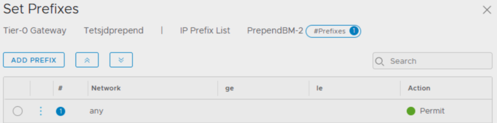
IP Prefix Lists
We need to create two IP prefix lists separated as in the Route Map configuration we can’t assign twice the same IP prefix list.
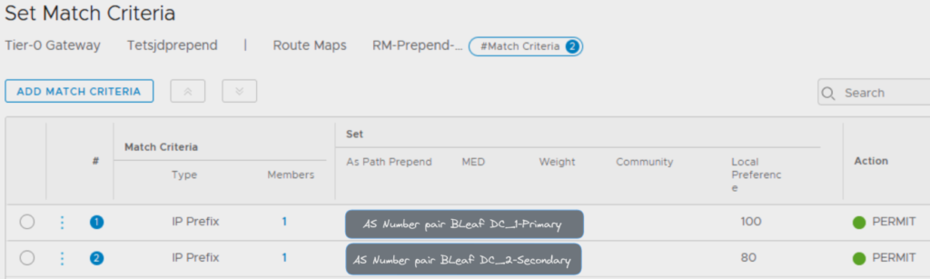
Route Map
We can now create a Route Map using the two IP prefix lists on the Match Criteria Members.
Here we assign the value for the AS path prepend.
By default the value is 100, the path with the highest value is preferred.
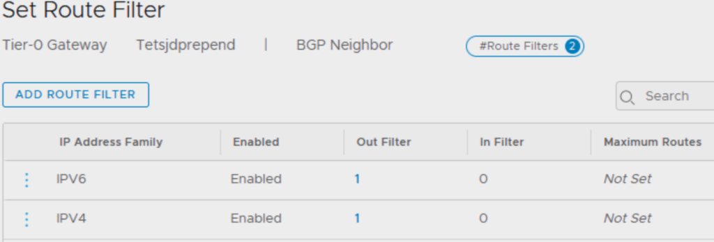
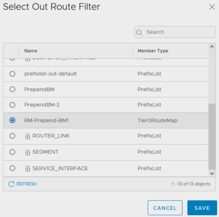
Set Route Filter to BGP Neighbors
Once the Route Map is created we can apply it under the BGP Neighbors for IPv4 and/or IPv6 IP Address Family.